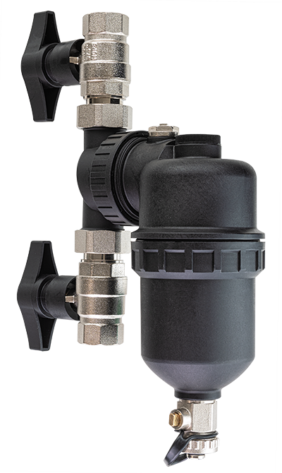
DEFMAG 2

Magnetic sludge separator

Magnetic sludge separator for systems up to 35 kW

Mayline DEFMAG 2 is a magnetic sludge separator that, developping an a helicoidal action, is able to separate and remove all impurities, such as iron oxide, sludge, various types of deposits, sand, etc. from the system water. Mayline DEFMAG 2 is suitable for use in all domestic systems and is installed in the return circuit, at the boiler inlet, to prevent impurities from being deposited inside the heat exchanger. Mayline DEFMAG 2 is very versatile thanks to the swivel diverter body and also allows for vertical or diagonal installation without compromising performance.

Features

  • Helicoidal technology with 12,000 Gauss Neodymium magnet;
  • Installation on both horizontal and vertical pipes via an adjustable ring nut;
  • Vertical or 45° inclined installation; • Removes any magnetic and non-magnetic particles;
  • Non-stick filter in flow direction to ensure decantation of non-magnetic impurities;
  • Self-cleaning: easy cleaning and rinsing via a drain valve;
  • Low pressure drop;
  • Suitable for heating, cooling, heat pumps, biomass installations, etc.;
  • Resistant up to 90° C;
  • Suitable for glycol solutions;
  • Anti-stripping wrench supplied.

Description

Code | Package: MY/DEFMAG2 | 1 piece
Important note: In case of first-time application, clean the sludge separator after 4-5 weeks. Subsequent cleaning must be carried out every 6 to 12 months.
Instructions for use: 1. On the system return line, locate an installation position that allows accessibility for maintenance, e.g. to remove the magnet in the upper body, open the filter drain tap, and/or disassemble the lower body for thorough cleaning.
2. Empty the system. If the system is treated with conditioning agents, it is advisable to collect the system water in a special container so that it can be used at the end of the work.
3. Always use the ball valves supplied when installing the sludge separator to facilitate maintenance, cleaning and flushing operations. It is recommended to measure the sludge separator with the valves installed as if they were running, in order to cut the chosen return pipe according to the total installation size.
4. During installation, turn the ring nut of the sludge separator with the arrow on the diverter body pointing in the direction of the system flow. Check that the O-ring is in its seat, then tighten. The fi lter housing can be oriented vertically or tilted by up to 45° in case of limited space.
5. A thorough cleaning is recommended with one of the Mayline HRplus, Mayline HR or Mayline CP cleaners for high-temperature systems and with Mayline SB for low-temperature systems. In both cases, rinse thoroughly with tap water.
6. Open the ball valves to load the system. Add 1% Mayline K32 conditioning agent for high-temperature systems, or 1% Mayline SBA for low-temperature systems. Then check all seals on the sludge separator and ball valves. Vent the air in the sludge separator using the air exhaust valve on top of the sludge separator.

Scheda tecnica

Download

Technical Datasheet

Download